
跟着大佬的文章读一下 Linux 0.11 的源码
github.com/sunym1993/flash-linux0.11-talk
万事开头难 (bootsects.s)
从 0x7C00 开始的操作系统启动
开机首先会执行主板上的 BIOS 程序,BIOS 将启动区的 512 字节(一个扇区)复制到内存中的 0x7C00 地址,随后跳转到这个地址继续执行
启动区的识别:0 盘 0 道 1 扇区的 512 字节最后两个字节为
55 AA
所以操作系统将从第一扇区启动,这在源码中对应了 boot/bootsect.s 文件
最开始的两行源码:
mov ax, 0x07C0
mov ds, ax
将 ds 寄存器赋值为 0x7C0
为了能够在 16 位实模式下访问 20 位的地址,在读取段寄存器时需要
<< 4,所以ds是0x7C0时对应了地址0x7C00,指向了此时代码段的地址,方便了后续对内存的访问
给自己挪个地方
随后执行:
mov ax, 0x9000
mov es, ax
mov cx, #256
sub si, si
sub di, di
rep movw
前面两行和最开始的两行类似,将 es 寄存器赋值为 0x9000,随后 cx = 0x100; si = 0; di = 0,最后循环执行 movw 指令
rep指令执行次数取决于cx,配合movw指令从ds复制到es
这里就将 0x7C00 处的 512 字节(256 WORDS)复制到了 0x90000 处
jmpi go, 0x9000
go:
  mov ax, cs
  ...
相当于 jmp go+0x90000,配合一下上面的复制指令,虽然执行的指令与实际地址后面这条指令相同,但实际地址已经挪过去了
正所谓《给自己挪个地方》
一些基础工作
go 后面的指令
go:
  mov ax, cs
  mov ds, ax
  mov es, ax
  mov ss, ax
  mov sp, #0xFF00
之前 jmpi 指令后,cs 寄存器就被复制为 0x9000,随后将 ds, es, ss 都赋值为了 0x9000,栈顶地址则被赋值为 ss:sp=0x9FF00
简单画一下目前的内存情况
+-----------------+ 0x90000 <- cs, ds, es, ss
|  mov ax, 0x7c0  |
|     ......      |
| mov sp, #0xFF00 |
|     next i      | <- ip
|     ......      |
+-----------------+
|     stack       |
+-----------------+ 0x9FF00 <- ss:sp
把硬盘里的其他部分也挪过来
在完成基本工作后
load_setup:
  mov dx, #0x0000   ; drive 0, head 0
  mov cx, #0x0002   ; sector 2, track 0
  mov bx, #0x0200   ; address = 512, in 0x9000
  mov ax, #0x0200+SETUPLEN ; SETUPLEN = 4, service 2, nr of sectors
  int 0x13          ; read it
  jnc ok_load_setup ; ok - continue
  mov dx, #0x0000
  mov ax, #0x0000   ; reset the diskette
  int 0x13
  j   load_setup

ok_load_setup:
  ...
int 0x13 是 BIOS 中的中断,在这里执行了 BIOS 中读取磁盘的程序,结合上面设置好的参数,就是将 2 ~ 5 扇区的内容(setup.s 程序)读取到 0x90200 内存中,由于该中断具体实现在 BIOS 中,此处只关注结果即可
随后继续执行 ok_load_setup
ok_load_setup:
  ; Get disk drive parameters, specifically nr of sectors/track
  ...
  ; Print some inane message
  ...
  ; Load the system (at 0x10000)
  mov ax, #0x1000
  mov es, ax
  call read_it    ; This routine loads the system at address 0x10000, making sure no 64KB boundaries are crossed.
  ; Check which root-device to use
  ...
  ; jump to the setup-routine loaded directly after the bootblock
  jmpi 0, SETUPSEG ; SETUPSEG = 0x9020
省略的代码和主要逻辑无关(参考省略号前的注释),主要用于输出 Loading system 等内容
这几行代码主要是执行了 read_it 函数,将第 6 扇区开始的 240 个扇区读取到 0x10000 地址(剩余全部代码,开头为 head.s),具体的原理与此前相似,最后跳转到 0x90200 执行第二扇区的代码
此时的内存
+------------+ <- 0x7C00
| bootsect.s |
+------------+
|    ...     |
+------------+ <- 0x10000
|   head.s   |
|            |
|   system   |
|            |
|            |
+------------+
|    ...     |
+------------+ <- 0x90000
| bootsect.s |
+------------+ <- 0x90200
|            |
|  setup.s   |
|            |
+------------+
接下来就跳转到 setup.s 程序了,在第一个程序中,一个最明显的特征就是所有的地址都是写死的,比如从第 1 扇区挪到固定的地址
0x7C00,再挪到固定的地址0x90000,最后把剩下的东西也挪到固定的地址0x90200和0x10000,这些地址都是写死的,不能出现任何偏差,简单总结就是“强耦合”,把前后执行的每一条指令与相应的内存都安排好了
继续启动 (setup.s)
保护模式前的准备
上一段程序最后跳转到了 0x90200,也就是 setup.s 中的代码
start:
  mov ax, #0x9000 ; this is done in bootsect already, but...
  mov ds, ax
  mov ah, #0x03   ; read cursor pos
  xor bh, bh
  int 0x10        ; save it in  known place, con_init fetches
  mov [0], dx     ; it from 0x90000.
吐槽一下,前面清零用的是
sub ax, ax,这里怎么就用xor ax, ax了
int 0x10 中断仍然是 BIOS 中的中断,用于显示服务,当 AH = 3 时,用于获取光标的位置与形态,并保存到 dx 寄存器中,其中 dh 保存了行号,dl 保存了列号
最终将结果保存至了 0x90000 地址,用于后续初始化控制台
后续的代码都是在干类似的事情,获取环境的信息,然后保存到内存中
; Get memory size (extended mem, kB)
mov ah, #0x88
int 0x15
mov [2], ax

; Get vedio-card data:
mov ah, #0x0F
int 0x10
mov [4], bx   ; bh = display page
mov [6], ax   ; al = video mode, ah = window width

; Check for EGA/VGA and some config parameters
mov ah, #0x12
mov bl, #0x10
int 0x10
mov [8], ax
mov [10], bx
mov [12], cx

; Get hd0 data
mov ax, #0x0000
mov ds, ax
lds si, [4 * 0x41]
mov ax, #INITSEG
mov es, ax
mov di, #0x0080
mov cx, #0x10
rep movsb

; Get hd1 data
mov ax, #0x0000
mov ds, ax
lds si, [4 * 0x46]
mov ax, #INITSEG  ; INITSET = 0x9000
mov es, ax
mov di, #0x0090
mov cx, #0x10
rep movsb

; Check that there IS a hd1
...
依次获取了内存、显卡、显示方式、硬盘等信息,都是在调用 BIOS 中断并保存,没必要细看了,最后的内存如下表所示
| addr | length | info |
|---|---|---|
| 0x90000 | 2 | 光标位置 |
| 0x90002 | 2 | 扩展内存数 |
| 0x90004 | 2 | 显示页面 |
| 0x90006 | 1 | 显示模式 |
| 0x90007 | 1 | 字符列数 |
| 0x90008 | 2 | 未知 |
| 0x9000A | 1 | 显示内存 |
| 0x9000B | 1 | 显示状态 |
| 0x9000C | 2 | 显卡特性参数 |
| 0x9000E | 1 | 屏幕行数 |
| 0x9000F | 1 | 屏幕列数 |
| 0x90080 | 16 | 硬盘0参数 |
| 0x90090 | 16 | 硬盘1参数 |
| 0x901FC | 2 | 根设备号 |
这些地址也都是约定好的,后面需要用的时候从这里获取即可
接下来需要为进入保护模式做准备了
首先是关闭中断
; now we want to move to protected mode ...
cli       ; no interrupts allowed
BIOS 中断至此就不再调用了,接下来会用操作系统的中断覆盖此前 BIOS 提供的中断向量表
不过首先我们需要将操作系统移动到正确的地址
; first we move the system to it's rightful place
mov ax, #0x0000
cld                 ; 'direction'=0, movs moves forward
do_move:
  mov es, ax        ; destination segment
  add ax, #0x1000
  cmp ax, #0x9000
  jz end_move
  mov ds, ax        ; source segment
  sub di, di
  sub si, si
  mov cx, #0x8000
  rep movsw
  jmp do_move

; then we load the segment descriptors
end_move:
  ...
这里做的操作与之前从 0x7C00 挪到 0x90000 是类似的,这里的效果就是将 0x10000 ~ 0x90000 的内存(后 240 个扇区的代码)移动到 0x0 ~ 0x80000(用了个 while 循环,每次挪 0x10000 字节)
段寄存器的历史包袱
实模式下的段基址:
$[ds:3] = (ds « 4) + 3$
保护模式下的段保护子则复杂多了,因为使用了分段机制,该机制下段寄存器中存放的是段选择子,使用段选择子到段描述符表(GDT, Global Descriptor Table)中找到所需要的段描述符,段描述符中存放的是真正的段基址,该地址再加上偏移得到物理地址
Linear Address Space
+------------------+ <- GDTR (a register)
| Descriptor Table |
|                  |
|                  |
|                  |
|  +------------+  |
|  | Descriptor |<-|------------+
|  +------------+  |            |
|        |         |            |
+------------------+            |
         |                      |
         V                  Selector:Offset (Logical Address)
+------------------+                   |
|     Segment      |                   |
|                  |                   |
|  +------------+  |                   |
|  |    Data    |<-|-------------------+
|  +------------+  |
|                  |
|                  |
|                  |
|                  |
+------------------+
所以,要想进入保护模式,必须要对寻址部分进行初始化
; Then we load the segment descriptors
lidt idt_48   ; load idt with 0, 0
lgdt gdt_48   ; load gdt with whatever appropriate
在源码末尾可以看到 idt_48 和 gdt_48 的定义
idt_48:
  .word 0     ; idt limit = 0
  .word 0, 0  ; idt base = 0L

gdt_48:
  .word 0x800 ; gdt limit = 0x800, 256 GDT entries
  .word 512+gdt, 0x9  ; get base = 0x9XXXX
这里 gdt_48 是一个 48 位数据,其中,高 32 位存储了全局描述符表 gdt 的内存地址,低 16 位则为表界限
gdt_48:
high                low
+-------------+-------+
| 00 09 xx xx | 08 00 |
+-------------+-------+
这里 gdt 的地址手动加上了 0x90200 的偏移
指令 lgdt 的用处就是将 gdt 位置信息存入 gdtr 寄存器
gdt 标签也在源码的最后,这就是 gdt 表中的真实数据了
gdt:
  .word 0, 0, 0, 0  ; dummy
  .word 0x07FF      ; 8Mb - limit=2047 (2048 * 4096 = 8Mb)
  .word 0x0000      ; base address = 0
  .word 0x9A00      ; code read/exec
  .word 0x00C0      ; granularity=4096, 386

  .word 0x07FF      ; 8Mb - limit=2047 (2048 * 4096 = 8Mb)
  .word 0x0000      ; base address = 0
  .word 0x9200      ; data read/exec
  .word 0x00C0      ; granularity=4096, 386
这里写了三个段描述符,段描述符的具体结构如下 (from Wiki Pedia)
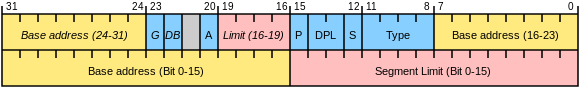
- Base Address
- Starting memory address of the segment. Its length is 32 Bit and it is created of the lower Part Bit 16 to 31, and the upper Part Bit 0 to 7, followed by Bit 24 to 31.
- Segment Limit
- Its length is 20 bit and is created of the lower Part Bit 0 to 15 and the upper Part Bit 16 to 19. It defines the address of the last accessible data. The length is one more than the value stored here. How exactly this should be interpreted depends on the Granularity bit of the segment descriptor.
- G=Granularity
- If clear, the limit is in units of bytes, with a maximum of 220 bytes. If set, the limit is in units of 4096-byte pages, for a maximum of 232 bytes.
- D/B
- D = Default operand size : If clear, this is a 16-bit code segment; if set, this is a 32-bit segment.
- B = Big: If set, the maximum offset size for a data segment is increased to 32-bit 0xffffffff. Otherwise it’s the 16-bit max 0x0000ffff. Essentially the same meaning as “D”.
- L=Long
- If set, this is a 64-bit segment (and D must be zero), and code in this segment uses the 64-bit instruction encoding. “L” cannot be set at the same time as “D” aka “B”. (Bit 21 in the image)
- AVL=Available
- For software use, not used by hardware (Bit 20 in the image with the label A)
- P=Present
- If clear, a “segment not present” exception is generated on any reference to this segment
- DPL=Descriptor privilege level
- Privilege level (ring) required to access this descriptor
- Type
- If set, this is a code segment descriptor. If clear, this is a data/stack segment descriptor, which has “D” replaced by “B”, “C” replaced by “E"and “R” replaced by “W”. This is in fact a special case of the 2-bit type field, where the preceding bit 12 cleared as “0” refers to more internal system descriptors, for LDT, LSS, and gates.
- C=Conforming
- Code in this segment may be called from less-privileged levels.
- E=Expand-Down
- If clear, the segment expands from base address up to base+limit. If set, it expands from maximum offset down to limit, a behavior usually used for stacks.
- R=Readable
- If clear, the segment may be executed but not read from.
- W=Writable
- If clear, the data segment may be read but not written to.
- A=Accessed
- This bit is set to 1 by hardware when the segment is accessed, and cleared by software.
根据上述信息,可以对应到三个描述符
第一个为空
根据高 22 位 (B/D) 表示代码段或数据段,可知第二个为代码段描述符,第三个为数据段描述符,基址均为 0(这样设置,在保护模式的寻址结果中,物理地址与逻辑地址完全相同)
另一个重要的东西是 idt (中断描述符表),同样有一个 idtr 指向 idt,原理与 gdt 相同,此处指令暂时将 idtr 清空了,后面才会重新设置
在进入保护模式前,再看一下此时的内存情况:
+--------------+ <- 0x00000
|    system    |
| from 6 ~ 246 |
+--------------+ <- 0x80000
|     ...      |
+--------------+ <- 0x90000
|  Some  Data  |
+--------------+ <- 0x90200
|              |
|   setup.s    |
|     idt      | <- idtr
|     gdt      | <- gdtr
|              |
+--------------+
|     ...      |
+--------------+
|     Stack    |
+--------------+ <- 0x9FF00
保护模式:漫长的前摇,简单的切换
赋值完 idtr 和 gdtr 后,要打开 A20 地址线
; that was painless, now we enable A20
call empty_8042
mov al, #0xD1     ; command write
out #0x64, al
call empty_8042
mov al, #0xDF     ; A20 on
out #0x60, al
call empty_8042
about
empty_8042: This routine checks that the keyboard command queue is empty. No timeout is used - if this hangs there is someting wrong with the machine, and we probably couldn’t proceed anyway.
简单来说就是检查输入缓冲区是否为空,可以忽略
打开 A20 地址线这里其实又是对 CPU 的控制了,32 位 CPU 考虑到兼容性,必须手动设置才能开启 32 位模式,这里就是手动设置环节
; Now we have to reprogram the interrupts.
; We put them right after the intel-reserved hardware interrupts, at int 0x20-0x2F.
; There they won't mess up anything.
; Sadly IBM really messed this up with the original PC, and they haven't been able to rectify it afterwards.
; Thus th bios puts interrupts at 0x08-0x0F, witch is used for the internal hardware interrupts as well.
; We just have to reprogram the 8259's, and it isn't fun.

  mov al,#0x11        ; initialization sequence
                      ; 其中 0x11 表示初始化命令的开始,ICW1 命令字,表示边沿触发、多片 8259 级连,最后发送 ICW4 命令字
  out #0x20,al        ; send it to 8259A-1
                      ; 将命令发送至芯片 8259A-1
  .word   0x00eb,0x00eb       ; jmp $+2, jmp $+2
                      ; 这两条指令相当于 nop,用于延时,直接用机器语言的写法挺有意思
  out #0xA0,al        ; and to 8259A-2
                      ; 同样也给 8259A-2 芯片
  .word   0x00eb,0x00eb
  mov al,#0x20        ; start of hardware int's (0x20)
  out #0x21,al        ; 这里 0x21 是 8259A-1(主芯片),0xA1 是 8259A-2(从芯片)
                      ; 设置起始中断号为 0x20
  .word   0x00eb,0x00eb
  mov al,#0x28        ; start of hardware int's 2 (0x28)
  out #0xA1,al        ; 设置从芯片起始中断号为 0x28
  .word   0x00eb,0x00eb
  mov al,#0x04        ; 8259-1 is master
  out #0x21,al        ; 这里设置的主从芯片,ICW3 命令字将主芯片的 IR2 连接从芯片的 INT
  .word   0x00eb,0x00eb
  mov al,#0x02        ; 8259-2 is slave
  out #0xA1,al        ; 将从芯片的 INT 连到主芯片的 IR2
  .word   0x00eb,0x00eb
  mov al,#0x01        ; 8086 mode for both
  out #0x21,al
  .word   0x00eb,0x00eb
  out #0xA1,al        ; 向主从芯片发送 ICW4 命令字,进入 8086 模式
  .word   0x00eb,0x00eb
  mov al,#0xFF        ; mask off all interrupts for now
  out #0x21,al
  .word   0x00eb,0x00eb
  out #0xA1,al        ; 屏蔽主从芯片所有中断请求
这里都是对可编程终端控制器 8259 芯片进行的编程,整合了一下中文注释(from github.com/beride/linux0.11-1)
前摇很长,但真正的切换只有下面几行
mov ax, #0x0001   ; protected mode (PE) bit
lmsw ax           ; This is it
jmpi 0, 8         ; jmp offset 0 of segment 8 (cs)
lmsw 命令将 cr0 寄存器的末尾(PE)赋值为 ax=1,这就开启保护模式了
而这个 jmpi 命令中过,后面的 8 表示是段选择子,0 表示偏移地址,这里的索引方式已经变成了保护模式下的索引方式了,所以根据段选择子的结构,描述符索引为 1,根据之前对 gdt 的定义,对应的描述符是
.word 0x7FFF  ; 8Mb - limit = 2047
.word 0x0000  ; base address = 0
.word 0x9A00  ; code read/exec
.word 0x00C0  ; granularity=4096, 386
所以这里的段选择子指向的是代码段描述符,段基址为 0,所以最终结构为跳转到地址为 0 继续执行
根据此前的地址设置,0 这个地址就是 240 个扇区的指令,对应 head.s 和 main.c 及其他各模块的操作系统代码
到这里,就要正式进入操作系统了
总算是进入操作系统了 (head.s)
再来一次初始化
正经的源码在这里换成了 AT&T 格式,很烦,还好大佬的文章还是用的 intel 格式
_pg_dir:
_setartup_32:
  mov eax, 0x10
  mov ds, ax
  mov es, ax
  mov fs, ax
  mov gs, ax
  lss esp, _stack_start
_pg_dir 表示页目录,设置分页机制的时候会用到
将 ds 到 gs 四个段寄存器都赋值为 0x10,按照段选择子,这几个段寄存器都指向了此前 gdt 中,描述符索引为 2 的描述符,也就是数据段描述符
lss 指令相当于让 ss:esp 栈顶指针指向 _stack_start,这在 sched.c 中定义
long user_stack[4096 >> 2];

struct {
  long *a;
  short b;
} stack_start = {&user_stack[4096 >> 2], 0x10};
根据这个定义,0x10 将会赋值给 ss 寄存器(依然是数据段描述符,基址为 0),而 user_stack 的最后一个地址的后一个地址将会赋值给 esp,所以这个 user_stack 就是后面用到的栈了
call setup_idt
call setup_gdt
mov eax, 0x10
mov ds, ax
mov es, ax
mov fs, ax
mov gs, ax
lss esp, _stack_start
执行了设置 idt 和 gdt 的函数后,又把刚才的指令执行了一遍
这里的 setup_idt 子程序如下
; set up a idt with 256 entries pointint to ignore_int, interrupt gates.
; It then loads idt.
; Everything that wants to install itself in the idt-table may do so themselves.
; Interrupts are enabled elsewhere, when we can be relatively sure everything is ok.
; This routine whil be over-written by the page tables.
setup_idt:
  lea edx, ignore_int
  mov eax, 0x00080000
  mov ax, dx      ; selector = 0x0008 = cs
  mov dx, 0x8E00  ; interrupt gate - dpl=0, present
  lea edi, _idt
  mov ecx, 0x100
  rp_sidt:
    mov [edi], eax
    mov [edi+4], edx
    add edi, 8
    dec ecx
    jne rp_sidt
  lidt fword ptr idt_descr
  ret

idt_descr:
  dw 256 * 8 - 1
  dd _idt

_idt:
  DQ 256 dup(0)
使用了一个 0x100 次的 do while 循环对 _idt 进行初始化,每一次循环设置一个中断描述符,值均为 00 00 8E 00 00 08 ignore_int (地址由高到低),因此所有的 idt 均指向了 ignore_int 函数(默认中断函数),后面会逐渐替换
setup_gdt 如下
setup_gdt:
  lgdt gdt_descr
  ret
比较简单,就是将 gdt_descr 加载到 gdtr
长这样:
gdt_descr:
  .word 256 * 8 - 1         ; so does gdt (not that that's any
  .long _gdt                ; magic number, but it works for me :^)

  .align 3
_idt:
  .fill 256, 8, 0           ; idt is uninitialized

_gdt:
  .quad 0x0000000000000000  ; NULL descriptor
  .quad 0x00c09a0000000fff  ; 16Mb
  .quad 0x00c0920000000fff  ; 16Mb
  .quad 0x0000000000000000  ; TEMPORARY - don't use
  .fill 252, 8, 0
可以看到,给 idt 和 gdt 都预留了 256 * 8 字节的空间,而 gdt 的初始值为 NULL descriptor,共 64 项
这里重新设置的原因在于此前的内存已经不再使用(可以理解为
setup部分占的内存被 free 掉了),后续将用于存放其他内容,因此需要将idtr和gdtr指向这个新的idt和gdt表
开启分页机制
在执行完上面的代码后,是一些简单的检查:
检查 A20 开启(进入保护模式)
1:
  incl eax
  movl 0x000000, eax
  cmpl 0x100000, eax
  je 1b
检查芯片设置
; 486 should set bit 16, to check for wirte-protect in supervisor mode.
; Then it would be unnecessary with the "verify_area()"-calls.
; 486 users probably want to set the NE (#5) bit also, so as to use int 16 for math errors.
movl eax, cr0         ; check math chip
andl 0x80000011, eax  ; Save PG, ET, PE
orl eax, 2            ; set MP
testl eax, 0x10
jne 1f                ; ET is set - 387 is present
xorl eax, 6           ; else reset MP and set EM
1:
  movl cr0, eax
  jmp after_page_tables
在做完基本检查后,将跳转到分页模式
after_page_tables:
  pushl 0
  pushl 0
  pushl 0
  pushl L6
  pushl _main             ; 这里的压栈用于后续跳转到 _main
  jmp setup_paging
L6:
  jmp L6

setup_paging:
  movl ecx, 1024 * 5      ; 5 pages - pg_dir+4 page tables
  xorl eax, eax
  xorl edi, edi           ; pg_dir is at 0x000
  cld;rep;stosl
  movl eax, _pg_dir
  movl [_pg_dir]   , pg0+7  ; set present bit/user r/w
  movl [_pg_dir+4] , pg1+7
  movl [_pg_dir+8] , pg2+7
  movl [_pg_dir+12], pg3+7
  movl edi, pg3+4092
  movl eax, 0xfff007  ; 16Mb - 4096 + 7 (r/w user, p)
  std
1:
  stosl               ; fill pages backward - more efficient
  subl eax, 0x1000
  jge 1b
  xorl eax, eax       ; pg_dir is at 0x0000
  movl cr3, eax       ; cr3 - page directory start
  movl eax, cr0
  orl eax, 0x80000000
  movl cr0, eax       ; set paging (PG) bit
  ret                 ; this also flushes prefetch-queue
开启分页机制的设置在 ret 前的最后三条指令上,这三条指令的效果就是将 cr0 的最高位置为 1,这一位就是 PG 位,1 表示开启分页机制
这个版本的 Linux 只为内存预留了 16 Mb 的空间,最大地址为 0xFFFFFF,1 页为 4KB,1 页表为 1024 页,1页表目录为 1024 页表,因此只需要提供 1 页表目录和 4 页表即可,这也就对应了开头一些指令的含义
mov ecx, 1024 * 5 表示总共需要 5 页,而 pg_dir 就成功与上文 head.s 开头呼应上了,这个标签就是页表目录,而下面将存放四个页表
.org 0x1000 pg0;
.org 0x2000 pg1;
.org 0x3000 pg2;
.org 0x4000 pg3;
.org 0x5000
所以在经过这一步设置后,物理内存的 0x0000-0x5000 都是分页机制使用的空间了,最后将 cr3 赋值为 0,就是指向了 pg_dir 的地址
开启分页机制后,覆盖掉的空间是此前初始化 idt 和 gdt 的代码(占用空间为
0x0000-0x1000)
此外,pg?+7 中,pg? 部分是地址,因为后三位必须要对其到 0b000,所以正好用于表示权限,7=0x111 就表示页存在、用户可读写
在开启分页模式后,经过此前分段机制计算得到的地址为线性地址,需要再次经过分页机制计算才能得到物理地址:
前 10 bit 表示页目录项的索引,中间 10 bit 表示页表项的索引,最后 12 bit 表示页内的偏移,先找对应的页目录项,再找页表项,最后加上索引,就得到实际物理地址了
跳转到 main
这里跳转到 main 的方法和 ROP 很类似
after_page_tables:
  ...
  pushl _main
  jmp setup_paging

setup_paging:
  ...
  ret   ; ROP to _main
把 _main 的地址放到栈顶,然后用 jmp 指令跳转到另一个子程序,此时对栈本身没有进行改变,而 setup_paging 作为被 jmp 执行的程序,最后却 ret 了,这就相当于执行了一个 pop eip,结果就是 eip=_main
于是接下来就正式开始执行 _main 函数了
总结一下此时的内存情况
+--------------+ <- 0x00000 <- cr3
|    pg_dir    |
|     pg 0     |
|     pg 1     |
|     pg 2     |
|     pg 3     |
+--------------+ <- 0x05000
|              |
|    system    |
| from 6 ~ 246 |
|              |
|     idt      | <- idtr
|     gdt      | <- gdtr
|              |
|              |
|     512K     |
|              |
+--------------+ <- 0x80000
|     ...      |
+--------------+ <- 0x90000
|  Some  Data  |
+--------------+ <- 0x90200
|              |
|   setup.s    |
|              |
+--------------+
|     ...      |
+--------------+
|    Stack     |
+--------------+ <- 0x9FF00